Occasionally you will come across a CMOS circuit where the complementary nature of the n-channel pull-downs and p-channel pull-ups are not obvious, as in the circuit shown below:

- Construct a table that gives the on-off status of each transistor in the circuit above for all combinations of inputs A and B.
- Compute the output, Y, for each input combination and describe the function of the above circuit.
Solution:
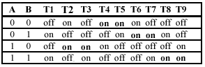
2. The output Y is connected to four pairs of transistors in series, so each of these pairs can affect the output.
when A=0 and B=0, transistors T4 and T5 are on, so Y=0
when A=0 and B=1, transistors T6 and T7 are on, so Y=1
when A=1 and B=0, transistors T2 and T3 are on, so Y=1
when A=1 and B=1, transistors T8 and T9 are on, so Y=0
Putting this together, we conclude that Y = XOR(A,B).
About the Author
Murugavel Ganesan
Product Director | SerDes · IVN · Edge AI · Compute | Ex Intel · Infineon
A semiconductor product leader working across product architecture, definition, strategy, and silicon and software execution, from concept through volume production. He has worked with teams across Asia, Europe and the USA, including at Intel, Infineon and ArrayComm.
His work covers ASICs, SoCs, FPGAs and chiplets for wireless, wireline, automotive, IoT and AI, including PCIe, CXL and DDR interfaces alongside RF and mixed-signal design.


Your comments will be moderated before it appears here.