

Question: What is the maximum distance of the I2C bus?
This depends on the load of the bus and the speed you run at. In typical applications, the length is a few meters (9-12ft). The maximum capacitive load has been specified (see also the electrical Spec's in the I2C FAQ). Another thing to be taken into account is the amount of noise picked up by long cabling. This noise can disturb the signal transmitted over the bus so badly that it becomes unreadable.
The length can be increased significantly by running at a lower clock frequency. One particular application - clocked at about 500Hz - had a bus length of about 100m (300ft). If you are careful in routing your PCB's and use proper cabling (twisted pair and/or shielded cable), you can also gain some length.
If you need to go far at high speed, you can use an active current source instead of a simple pull-up resistor. Philips has a standalone product for this purpose. Using a charge pump also reduces "ghost signals" caused by reflections at the end of the bus lines.
Question: I'd like to extend the I2C bus. Is there something like a repeater for I2C?
Yes indeed this exists. Philips manufactures a special chip to buffer the bi-directional lines of the I2C bus. Typically, this is a current amplifier. It forces current into the wiring (a couple of mA). That way you can overcome the capacitance of long wiring.
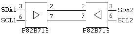 However, you will need this component on both sides of the line. The charge pump in this devices can deliver currents up to 30mA which is way too much for a normal I2C chip to handle. With these buffers you can handle loads up to 2nF. The charge amplifier 'transforms' this load down to a 200pF load which is still acceptable by I2C components.
Question: Are there stand-alone I2C controllers available?
Yes indeed. There is a special chip to do the I2C interfacing. The PCD8584 or PCF8584 incorporate a complete I2C interface. These chips are designed in such way that they can interface to almost any microcontroller around.
Question: Can I abort an ongoing I2C bus transmission?
Is it okay to abort an on-going transmission any time.
According to the specification, this should work. It depends on the layout of the component. A real I2C compatible IC will be able to handle this. It might make sense to test this before you use it.
Usually, when a START or STOP condition is detected, the internal logic of the chip is forced into a certain state. Internally, the logic that detects START and STOP is different from the logic that does all other processing. The START together with the address register is to be considered as a functional unit inside the chip.
When a START is detected, all internal operations are cancelled and the chip will compare the incoming data with its own address.
When a STOP is detected, ALL chips on the bus will reset their internal logic to IDLE mode except for the START detector (this is also used to cut power consumption). Therefore, when a start condition is issued on the bus, the START detector will 'wake-up' the rest of the internal logic.
Question: Do I need to generate an ACK in read mode on the last byte? My chip starts sending data and occupies the bus...
This is a somewhat puzzling question. Indeed this is a bit strange. Usually, if you have read the last byte in a chip and generate an ACK, the chip should do nothing anymore, so the bus should be clear for you to create a STOP condition. Apparently, there are some chips that start transmitting data again. One such chip is the PCF 8574 I/O expander.
Though not always desirable, this feature can come in handy. If you need to sample incoming data fast, then you just continue reading from the chip. This prevents that you lose 'arbitration' of the bus in a multi-master environment.
It also speeds things up. You don't have to address the chip over and over again so you save the time for START, Address, ACK and STOP stage for every next byte read. This can lead to a more than doubled transfer rate.
Question: Why does the SCL line have to be bi-directional?
The clock line needs to be bi-directional when using a MULTI-MASTER protocol and when using the synchronization protocol.
When you are using only one Master then this is not required since the clock will always be generated by this device. If you run Multi-master then this changes. One master must be able to receive data from another master. At that time it must be able to receive clock information via the clock line also.
Question: How can I monitor the I2C bus?
There are a few commercial I2C monitor / debuggers around that can do this. Information on these devices can be found here.
There is another possibility to do this: By using the stand-alone I2C controller PCF8584 from Philips. This chip has a certain mode in which it does not take part in the real I2C action but only records what is going on. It listens to all addresses, but does not generate any acknowledge. Using some software routines and a MCU you could build a universal I2C data logger.
Question: How can I test / debug the I2C bus?
There is no general way to debug an I2C bus. However, a few guidelines might help to get it running.First thing is to check the levels on the bus. You should see a clear signal that has a low level that is lower then 0.8 volt and a high level which is at least 3.5 volts.
If the high level is not high enough or does not rise fast enough then you can try to lower the value of the pull up resistor. You must take care however not to surpass the maximum allowable current in the I2C driver stage. The minimum allowable resistor for a 5 volt driven I2C bus is 5 V / 3mA = 1600 Ohms. A typical value of 4700 ohm should work fine.
Make sure the bus is not 'stuck' to '0'. This could be the result of a bad power supply (chips go into latch up during power-on) or a bad chip.
There are a few commercial I2C monitor / debuggers around. Information on these devices can be found here.
Question: Which microcontrollers do have an on-chip I2C interface?
A LOT of MCU's have a real I2C interface implemented in hardware, but this should not restrict the use of the I2C bus on other MCU's. ANY MCU can be made to talk to I2C using some small software routines.
There are microcontrollers with on-chip I2C modules as well as stand-alone I2C bus peripherals.
To list all the devices here would be impossible. A good overview can be found here: http://www.embeddedlinks.com/chipdir (search for keyword I2C)
Question: What bus speeds are available with I2C?
The bus speed for I2C was increased over the years. The following modes are available:
- Standard mode, with a bit rate up to 100kbit/s
- Fast-mode, with a bit rate up to 400 kbit/s
- High-speed mode (Hs-mode), with a bit rate up to 3.4 Mbit/s

a link to the old post on I2C...
ReplyDeletehttp://digitalelectronics.blogspot.com/2005/02/i2c-bus.html