


I2C interview questions usually test four things: the electrical limits of an open-drain bus (capacitance, pull-ups, distance), the protocol details (START, STOP, ACK and NACK, arbitration, clock stretching), the speed modes, and how you debug a stuck or noisy bus. The questions below cover each of these with practical answers. The key numbers to remember are a 400 pF bus capacitance limit for Standard and Fast mode, and speeds of 100 kbit/s, 400 kbit/s, 1 Mbit/s, 3.4 Mbit/s and 5 Mbit/s for the five modes.
Key takeaways
- I2C length is limited by total bus capacitance, not by a fixed distance. The specification limit is 400 pF in Standard and Fast mode (550 pF in Fast-mode Plus).
- Pull-up resistor value has a minimum set by sink current and a maximum set by rise time.
- A master receiving data must send a NACK after the last byte it wants, then a STOP. Sending an ACK tells the slave to keep sending.
- SCL is bidirectional because of multi-master clock synchronisation and slave clock stretching.
- Bus buffers and extenders (such as the Philips, now NXP, P82B715) let a bus drive long cables by working at higher current.
Electrical questions
Question: What is the maximum distance of the I2C bus?
This depends on the load of the bus and the speed you run at. In typical applications, the length is a few metres (9 to 12 ft). The specification does not give a length; it limits the maximum capacitive load, which is 400 pF for Standard and Fast mode. Another thing to take into account is the noise picked up by long cabling. This noise can disturb the signal so badly that it becomes unreadable.
A quick estimate shows why a few metres is typical. Suppose each device adds 10 pF, there are eight devices, and the cable adds about 60 pF per metre (an illustrative figure; check your cable's data sheet). Devices use 80 pF, leaving 320 pF for cable: about 5 m before the 400 pF limit, with no margin.
The length can be increased significantly by running at a lower clock frequency, because a slower clock tolerates a slower rise time. One particular application, clocked at about 500 Hz, had a bus length of about 100 m (300 ft). If you are careful in routing your PCBs and use proper cabling (twisted pair and/or shielded cable), you can also gain some length.
If you need to go far at high speed, you can use an active current source instead of a simple pull-up resistor. Philips (now NXP) made standalone products for this purpose. Such drivers are also reported to reduce "ghost signals" caused by reflections at the end of the bus lines.
Question: I'd like to extend the I2C bus. Is there something like a repeater for I2C?
Yes, this exists. Philips made a special chip to buffer the bidirectional lines of the I2C bus, the P82B715 bus extender shown below. It works as a current amplifier: it forces more current into the wiring (several mA), and that way you can overcome the capacitance of long wiring.
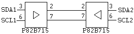
You need this component on both sides of the line. The buffered side in these devices can sink currents up to 30 mA, which is far too much for a normal I2C chip to handle. With these buffers you can handle loads up to 2 nF. The amplifier transforms this load down to a 200 pF load, which is still acceptable to I2C components. Today there are also many I2C repeaters, hub buffers and differential extenders from several vendors, some of which carry I2C over twisted pair for tens of metres.
Question: How do I choose the pull-up resistor?
The pull-up has a minimum and a maximum value.
- Minimum, set by the sink current. A Standard or Fast mode device must pull the line to no more than 0.4 V while sinking 3 mA. So Rp(min) = (VDD - 0.4 V) / 3 mA. At 5 V this is 4.6 / 0.003 = about 1.53 kOhm.
- Maximum, set by the rise time. The rise time from 30% to 70% of VDD is about 0.8473 x Rp x Cb. Standard mode allows 1000 ns, Fast mode 300 ns, Fast-mode Plus 120 ns. So Rp(max) = tr / (0.8473 x Cb).
Worked example: Fast mode with Cb = 200 pF gives Rp(max) = 300 ns / (0.8473 x 200 pF) = about 1.77 kOhm. At 5 V the window is 1.53 to 1.77 kOhm, which is narrow. In Standard mode with 100 pF, Rp(max) is about 11.8 kOhm, so the common 4.7 kOhm value is comfortable. In Fast mode with 100 pF, Rp(max) is about 3.5 kOhm, so 4.7 kOhm is too weak.
Controller and protocol questions
Question: Are there stand-alone I2C controllers available?
Yes. There are special chips to do the I2C interfacing. The PCD8584 and PCF8584 incorporate a complete I2C interface, and are designed so that they can interface to almost any microcontroller. These are old parts; check current availability, as newer bridge chips (for example SPI-to-I2C or UART-to-I2C bridges) now fill this role.
Question: Can I abort an ongoing I2C bus transmission?
According to the specification, this should work, but it depends on how the component was designed. A truly I2C-compatible IC will handle it. It makes sense to test this before you rely on it.
Usually, when a START or STOP condition is detected, the internal logic of the chip is forced into a known state. Internally, the logic that detects START and STOP is separate from the logic that does all other processing. The START detector together with the address register can be considered as one functional unit inside the chip.
When a START is detected, all internal operations are cancelled and the chip compares the incoming data with its own address.
When a STOP is detected, the chips on the bus reset their internal logic to idle, except for the START detector (this is also used to cut power consumption). When a new START condition is issued on the bus, the START detector wakes up the rest of the internal logic.
If a slave is holding SDA low because a transfer was cut off mid-byte, the master can recover the bus by sending clock pulses on SCL (up to nine) until the slave releases SDA, then issuing a STOP. The I2C specification describes this bus clear procedure.
Question: Do I need to generate an ACK in read mode on the last byte? My chip starts sending data and occupies the bus.
No. When the master is the receiver, it must signal the end of the transfer by not acknowledging (NACK) the last byte, then generating a STOP. If the master sends an ACK on what it thinks is the last byte, the slave takes this as a request for another byte and starts driving the next data bit. If that bit is 0, SDA is held low and the master cannot generate a STOP. That is exactly the symptom in the question. One chip that behaves this way is the PCF8574 I/O expander, which keeps returning its port value for as long as the master keeps acknowledging.
Though not always wanted, this continuous-read behaviour can come in handy. If you need to sample incoming data fast, you just keep reading from the chip. In a multi-master system this also means you keep the bus and do not risk losing arbitration between reads.
It also speeds things up. You do not have to address the chip again for every byte, so you save the START, address, ACK and STOP for each new byte. This can more than double the transfer rate. In numbers: a fresh single-byte read costs about 20 bit times (START, 8 address bits and ACK, 8 data bits and ACK, STOP), while a continued read costs 9 bit times per byte. That is about 2.2 times faster.
Question: Why does the SCL line have to be bidirectional?
The clock line needs to be bidirectional when using multi-master operation and when using the clock synchronisation protocol.
When you use only one master, the clock is always generated by that device, so in the simplest systems SCL could be driven one way. With multiple masters this changes. Each master drives SCL as open drain, and the resulting clock is the wired-AND of all of them: a master must read SCL back to see when another master is holding it low. A master that loses arbitration must also be able to switch to receiving, including clock information from the line.
There is a second reason that applies even with one master: clock stretching. A slave that needs more time (for example an EEPROM finishing an internal operation, or a microcontroller slave servicing an interrupt) may hold SCL low. The master must sense this and wait, which needs SCL to be readable at the master.
Debug questions
Question: How can I monitor the I2C bus?
There are commercial I2C monitors and debuggers that can do this. Information on these devices can be found here. Most modern logic analysers and many oscilloscopes also include I2C protocol decoding.
Another possibility is the stand-alone I2C controller PCF8584 from Philips. It has a mode in which it does not take part in bus traffic but only records what is going on: it listens to all addresses but does not generate any acknowledge. With some software routines and a microcontroller you could build a universal I2C data logger.
Question: How can I test or debug the I2C bus?
There is no single general way to debug an I2C bus. However, a few guidelines help to get it running.
- Check the levels on the bus. On a 5 V bus you should see a clear low level below about 0.8 V and a high level of at least 3.5 V. For reference, the specification allows a receiver input low up to 0.3 x VDD and requires input high of at least 0.7 x VDD (3.5 V at 5 V), and a driver must pull low to 0.4 V or less at 3 mA. A low level near 0.8 V or higher suggests too strong a pull-up or a weak driver.
- Check the rise time. If the high level is not high enough or does not rise fast enough, try a lower pull-up value. Take care not to exceed the maximum allowed current in the I2C driver stage. The minimum resistor for a 5 V bus at 3 mA is about 1.5 kOhm (see the pull-up question above). A typical value of 4.7 kOhm works well for a lightly loaded Standard mode bus.
- Make sure the bus is not stuck at 0. This could be caused by a bad power supply (chips latching up during power-on), a bad chip, or a slave left mid-transfer after a reset. Try the bus clear procedure described above.
- Check addresses. Two devices with the same address, or confusion between 7-bit addresses and the 8-bit value including the read/write bit, are common causes of silence.
Commercial I2C monitors and debuggers are listed here.
Question: Which microcontrollers have an on-chip I2C interface?
A great many microcontrollers have a real I2C interface in hardware, but this should not restrict the use of I2C on other microcontrollers. Any microcontroller can be made to talk I2C using some small software routines (bit-banging).
There are microcontrollers with on-chip I2C modules as well as stand-alone I2C bus peripherals. Listing all of them here would be impossible. A good overview can be found at http://www.embeddedlinks.com/chipdir (search for the keyword I2C).
Question: What bus speeds are available with I2C?
The bus speed for I2C has been increased over the years. The following modes are defined:
| Mode | Maximum bit rate | Direction | Notes |
|---|---|---|---|
| Standard mode (Sm) | 100 kbit/s | Bidirectional | Original speed |
| Fast mode (Fm) | 400 kbit/s | Bidirectional | Most common today |
| Fast-mode Plus (Fm+) | 1 Mbit/s | Bidirectional | Stronger drivers (20 mA), 550 pF bus limit |
| High-speed mode (Hs-mode) | 3.4 Mbit/s | Bidirectional | Needs a master code and special current-source pull-up in the master |
| Ultra Fast-mode (UFm) | 5 Mbit/s | Unidirectional (write only) | Push-pull, no ACK; for devices such as LED drivers |
How interviewers probe I2C
- "Draw a START and a STOP condition." SDA falling while SCL is high is START; SDA rising while SCL is high is STOP. Data must be stable while SCL is high.
- "How does arbitration work?" Each master checks SDA after driving it. A master that drives 1 but reads 0 has lost and stops driving. Nobody's data is corrupted, because the winner never sees a difference.
- "Why open drain?" It allows the wired-AND needed for arbitration, clock synchronisation and clock stretching, and lets devices at different supply voltages share a bus with suitable level shifting.
- "Calculate the pull-up for this bus." Expect to give both limits, as in the worked example above.
FAQ
Who owns the I2C specification?
I2C was created by Philips Semiconductors, which became NXP in 2006. NXP publishes the specification as user manual UM10204.
Is SMBus the same as I2C?
SMBus is based on I2C and mostly compatible, but it adds timeouts, a minimum clock rate and different electrical levels, so check both specifications when mixing devices.
Can I2C run between boards?
Yes, over short distances directly, or over longer cables with buffers, extenders or differential I2C transceivers.

a link to the old post on I2C...
ReplyDeletehttp://digitalelectronics.blogspot.com/2005/02/i2c-bus.html